2024-09-28 13:05:29
www.righto.com
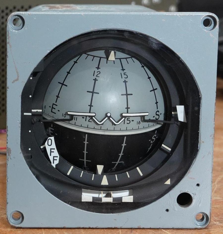
We recently received an attitude indicator for the F-4 fighter plane, an instrument that
uses a rotating ball to show the aircraft’s orientation and direction.
In a normal aircraft, the artificial horizon shows the orientation in two axes (pitch and roll), but the F-4 indicator
uses a rotating ball to show the orientation in three axes, adding azimuth (yaw).1
It wasn’t obvious to me how the ball could rotate in three axes: how could it turn in every direction and still remain
attached to the instrument?
The attitude indicator. The “W” forms a stylized aircraft. In this case, it indicates that the aircraft is climbing slightly. Photo from CuriousMarc.
We disassembled the indicator, reverse-engineered its 1960s-era circuitry, fixed some problems,2 and
got it spinning. The video clip below shows the indicator rotating around three axes.
In this blog post, I discuss the mechanical and electrical construction of this indicator.
(The quick explanation is that the ball is really two hollow half-shells attached to the internal mechanism at the “poles”; the shells rotate while the “equator” remains stationary.)
The F-4 aircraft
The indicator was used in the F-4 Phantom II3
so the pilot could keep track of the aircraft’s orientation during high-speed maneuvers.
The F-4 was a supersonic fighter manufactured from 1958 to 1981.
Over 5000 were produced, making it the most-produced American supersonic aircraft ever.
It was the main US fighter jet in the Vietnam War, operating from aircraft carriers.
The F-4 was still used in the 1990s during the Gulf War,
suppressing air defenses in the “Wild Weasel” role.
The F-4 was capable of carrying nuclear bombs.4
The F-4 was a two-seat aircraft, with the radar intercept office controlling radar and weapons
from a seat behind the pilot.
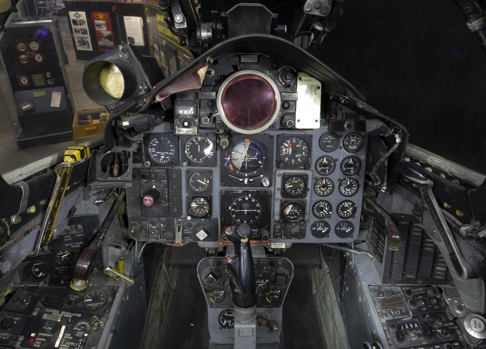
Both cockpits had a panel crammed with instruments, with additional instruments and controls on the sides.
As shown below, the pilot’s panel had the three-axis attitude indicator in the central position, just below the reddish radar scope, reflecting its importance.5
(The rear cockpit had a simpler two-axis attitude indicator.)
The attitude indicator mechanism
The ball inside the indicator shows the aircraft’s position in three axes.
The roll axis indicates the aircraft’s angle if it rolls side-to-side along its axis of flight.
The pitch axis indicates the aircraft’s angle if it pitches up or down.
Finally, the azimuth axis indicates the compass direction that the aircraft is heading,
changed by the aircraft’s turning left or right (yaw).
The indicator also has moving needles and status flags, but in this post I’m focusing
on the rotating ball.6
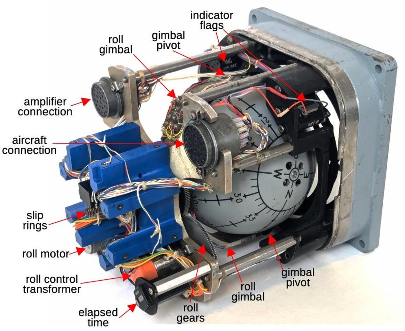
The indicator uses three motors to move the ball.
The roll motor (below) is attached to the frame of the indicator, while the pitch and azimuth motors are
inside the ball.
The ball is held in place by the roll gimbal, which is attached to the ball mechanism at the top
and bottom pivot points.
The roll motor turns the roll gimbal and thus the ball, providing a clockwise/counterclockwise
movement.
The roll control transformer provides position feedback.
Note the numerous wires on the roll gimbal, connected to the mechanism inside the ball.
The attitude indicator with the cover removed.
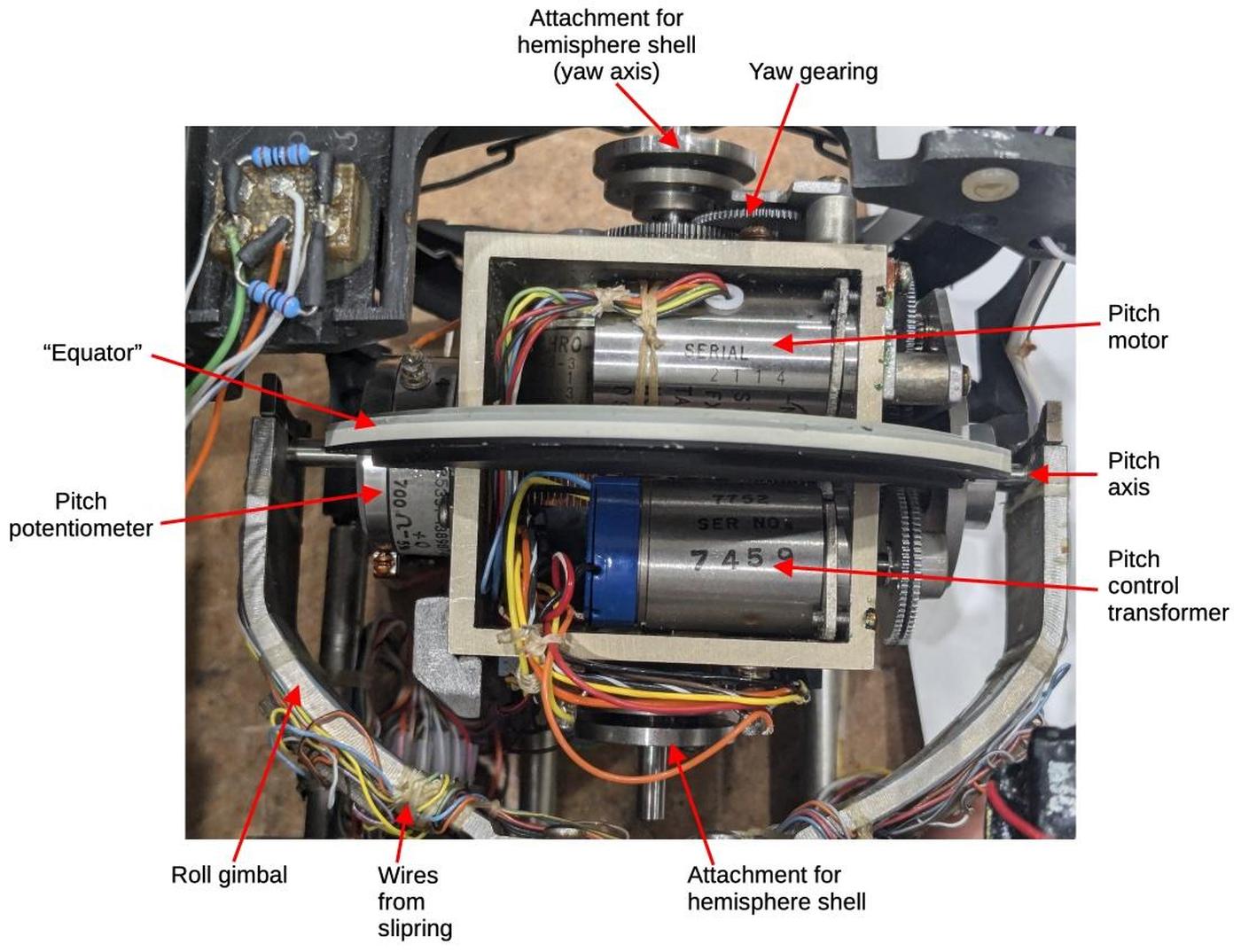
The diagram below shows the mechanism inside the ball, after removing the hemispherical
shells of the ball.
When the roll gimbal is rotated, this mechanism rotates with it.
The pitch motor causes the entire mechanism to rotate around the pitch axis (horizontal here), which is attached along the “equator”.
The azimuth motor and control transformer are behind the pitch components, not visible in this photo.
The azimuth motor turns the vertical shaft.
The two hollow hemispheres of the ball attach to the top and bottom of the shaft.
Thus, the azimuth motor rotates the ball shells around the azimuth axis, while the mechanism itself
remains stationary.
The components of the ball mechanism.
Why doesn’t the wiring get tangled up as the ball rotates?
The solution is two sets of slip rings to implement the electrical connections.
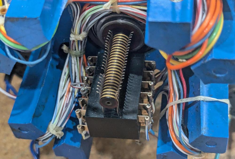
The photo below shows the first slip ring assembly, which handles rotation around the roll axis.
These slip rings connect the stationary part of the instrument to the
rotating roll gimbal.
The black base and the vertical wires are attached to the instrument,
while the striped shaft in the middle rotates with the ball assembly housing.
Inside the shaft, wires go from the circular metal contacts to
the roll gimbal.
The first set of slip rings. Yes, there is damage on one of the slip ring contacts.
Inside the ball, a second set of slip rings
provides the electrical connection between the
wiring on the roll gimbal and the ball mechanism.
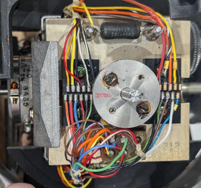
The photo below shows the connections to these slip rings, handling rotation around
the pitch axis (horizontal in this photo).
(The slip rings themselves are inside and are not visible.)
The shaft sticking out of the assembly rotates around the azimuth (yaw) axis. The ball hemisphere is attached to the metal disk.
The azimuth axis does not require slip rings since only the ball shells rotates; the electronics remain stationary.
Connections for the second set of slip rings.
The servo loop
In this section, I’ll explain how the motors are controlled by servo loops.
The attitude indicator is driven by an external gyroscope, receiving electrical signals indicating the roll, pitch, and azimuth positions.
As was common in 1960s avionics, the signals are transmitted from synchros, which use three wires to indicate an angle.
The motors inside the attitude indicator rotate until the indicator’s angles for the three axes match the input angles.
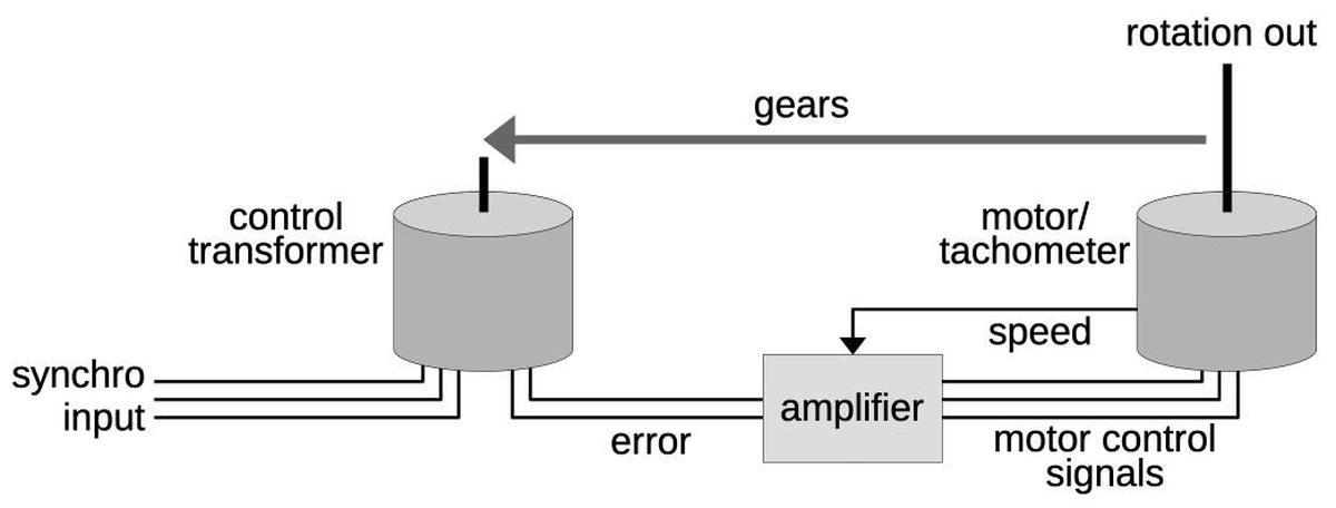
Each motor is controlled by a servo loop, shown below.
The goal is to rotate the output shaft to an angle that exactly matches the input angle,
specified by the three synchro wires.
The key is a device called a control transformer, which takes the three-wire input angle and a physical shaft rotation, and
generates an error signal indicating the difference between the desired angle and the physical angle.
The amplifier drives the motor in the appropriate direction until the error signal drops to zero.
To improve the dynamic response of the servo loop, the tachometer signal is used as a negative feedback voltage.
This ensures that the motor slows as the system gets closer to the right position, so the motor doesn’t overshoot the position and oscillate.
(This is sort of like a PID controller.)
This diagram shows the structure of the servo loop, with a feedback loop ensuring that the rotation angle of the output shaft matches the input angle.
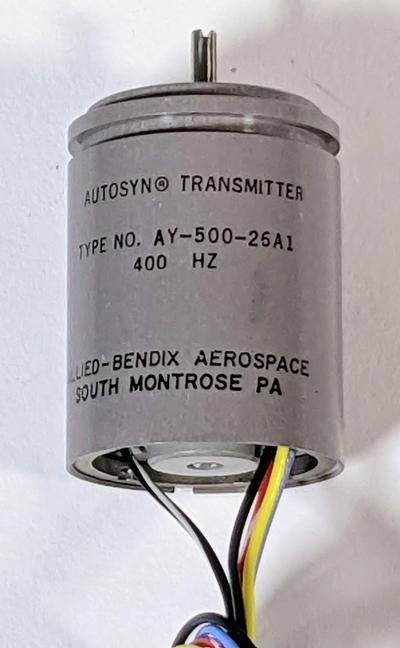
In more detail, the external gyroscope unit contains synchro transmitters, small devices that convert the angular position of a shaft
into AC signals on three wires.
The photo below shows a typical synchro, with the input shaft on the top and five wires
at the bottom: two for power and three for the output.
A synchro transmitter.
Internally, the synchro has a rotating winding called the rotor that is driven with 400 Hz AC.
Three fixed stator windings provide the three AC output signals. As the shaft rotates, the phase and voltage of the
output signals changes, indicating the angle.
(Synchros may seem bizarre, but they were extensively used in the 1950s and 1960s to
transmit angular information in ships and aircraft.)
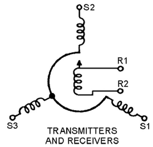
The schematic symbol for a synchro transmitter or receiver.
The attitude indicator uses control transformers to process these input signals.
A control transformer is similar to a synchro in appearance and construction, but it is wired differently.
The three stator windings receive the inputs and the rotor winding provides the error output.
If the rotor angle of the synchro transmitter and control transformer are the same, the signals cancel out and there is
no error output.
But as the difference between the two shaft angles increases, the rotor winding produces an error signal. The phase of the
error signal indicates the direction of error.
The next component is the motor/tachometer, a special motor that was often used in avionics servo loops.
This motor is more complicated than a regular electric motor.
The motor is powered by 115 volts AC, 400-Hertz, but this isn’t sufficient to get the motor spinning.
The motor also has two low-voltage AC control windings. Energizing a control winding will cause the
motor to spin in one direction or the other.
The motor/tachometer unit also contains a tachometer to measure its rotational speed, for use in a feedback loop.
The tachometer is driven by another 115-volt AC winding and generates a low-voltage AC signal proportional to the rotational speed
of the motor.
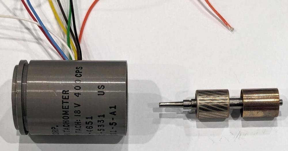
A motor/tachometer similar (but not identical) to the one in the attitude indicator).
The photo above shows a motor/tachometer with the rotor removed.
The unit has many wires because of its multiple windings.
The rotor has two drums. The drum on the left, with the spiral stripes, is for the motor. This drum is a “squirrel-cage rotor”,
which spins due to induced currents.
(There are no electrical connections to the rotor; the drums interact with the windings through magnetic fields.)
The drum on the right is the tachometer rotor; it induces a signal in the output winding proportional to the speed due to eddy currents.
The tachometer signal is at 400 Hz like the driving signal, either in phase or 180º out of phase, depending on the direction
of rotation.
For more information on how a motor/generator works, see my teardown.
The amplifier
The motors are powered by an amplifier assembly that contains three separate error amplifiers,
one for each axis.
I had to reverse engineer the amplifier assembly in order to get the indicator working.
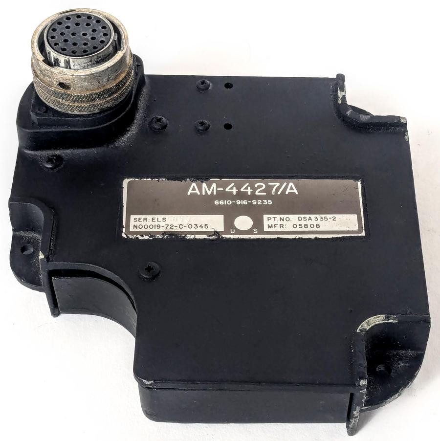
The assembly mounts on the back of the attitude indicator and connects to one of the
indicator’s round connectors. Note the cutout in the lower left of the amplifier assembly to
provide access to the second connector on the back of the indicator.
The aircraft connects to the indicator through
the second connector and the indicator passes the input signals to the amplifier through
the connector shown above.
The amplifier assembly.
The amplifier assembly contains three amplifier boards (for roll, pitch, and azimuth),
a DC power supply board, an AC transformer,
and a trim potentiometer.7
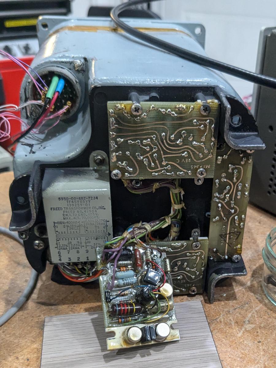
The photo below shows the amplifier assembly mounted on the back of the instrument.
At the left, the AC transformer produces the motor control voltage and powers the power supply board,
mounted vertically on the right.
The assembly has three identical amplifier boards; the middle board has been unmounted to show the components.
The amplifier connects to the instrument through a round connector below the transformer.
The round connector at the upper left is on the instrument case (not the amplifier) and provides the connection between the
aircraft and the instrument.8
The amplifier assembly mounted on the back of the instrument. We are feeding test signals to the connector in the upper left.
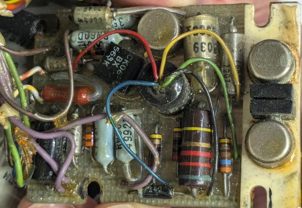
The photo below shows one of the three amplifier boards. The construction is unusual, with some components stacked on top of
other components to save space.
Some of the component leads are long and protected with clear plastic sleeves.
The board is connected to the rest of the amplifier assembly through a bundle of point-to-point wires, visible on the left.
The round pulse transformer in the middle has five colorful wires coming out of it.
At the right are the two transistors that drive the motor’s control windings, with two capacitors between them.
The transistors are mounted on a heat sink that is screwed down to the case of the amplifier assembly for cooling.
The board is covered with a conformal coating to protect it from moisture or contaminants.
One of the three amplifier boards.
The function of each amplifier board is to generate the two control signals so the motor rotates in the appropriate direction
based on the error signal fed into the amplifier.
The amplifier also uses the tachometer output from the motor unit to slow the motor as the error signal decreases, preventing
overshoot.
The inputs to the amplifier are 400 hertz AC signals, with the phase indicating positive or negative error.
The outputs drive the two control windings of the motor, determining which direction the motor rotates.
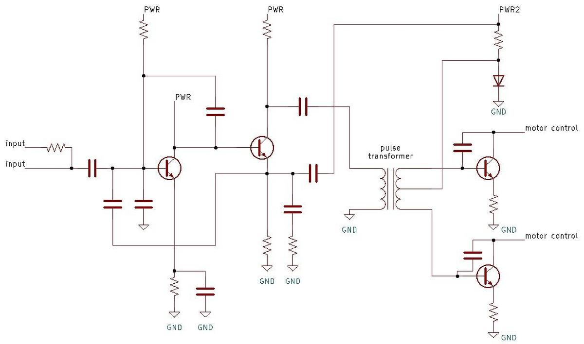
The schematic for the amplifier board is below.
The two transistors on the left amplify the error and tachometer signals, driving the pulse transformer.
The outputs of the pulse transformer will have opposite phase, driving the output transistors for opposite halves of
the 400 Hz cycle.
One of the transistors will be in the right phase to turn on and pull the motor control AC to ground, while the other
transistor will be in the wrong phase.
Thus, the appropriate control winding will be activated (for half the cycle), causing the motor to spin in the desired direction.
Schematic of one of the three amplifier boards. (Click for a larger version.)
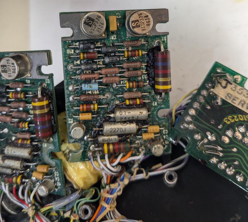
It turns out that there are two versions of the attitude indicator that use incompatible amplifiers.
I think that the motors for the newer indicators have a single control winding rather than two.
Fortunately, the connectors are keyed differently so you can’t attach the wrong amplifier.
The second amplifier (below) looks slightly more modern (1980s) with a double-sided circuit board and more components in place of the
pulse transformer.
The second type of amplifier board.
The pitch trim circuit
The attitude indicator has a pitch trim knob in the lower right, although the knob was missing from ours.
The pitch trim adjustment turns out to be rather complicated.
In level flight, an aircraft may have its nose angled up or down slightly to achieve the desired angle of attack.
The pilot wants the attitude indicator to show level flight, even though the aircraft is slightly angled, so the indicator can be
adjusted with the pitch trim knob.
However, the problem is that a fighter plane may, for instance, do a vertical 90º climb. In this case, the attitude indicator
should show the actual attitude and ignore the pitch trim adjustment.
I found a 1957 patent that explained how this is implemented.
The solution is to “fade out” the trim adjustment when the aircraft moves away from horizontal flight.
This is implemented with a special multi-zone potentiometer that is controlled by the pitch angle.
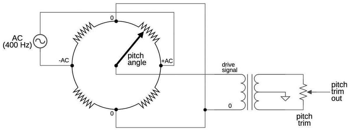
The schematic below shows how the pitch trim signal is generated from the special pitch angle potentiometer and the
pilot’s pitch trim adjustment.
Like most signals in the attitude indicator, the pitch trim is a 400 Hz AC signal, with the phase indicating positive or
negative.
Ignoring the pitch angle for a moment, the drive signal into the transformer will be AC.
The split windings of the transformer will generate a positive phase and a negative phase signal. Adjusting the pitch
trim potentiometer lets the pilot vary the trim signal from positive to zero to negative, applying the desired correction to
the indicator.
Now, look at the complex pitch angle potentiometer. It has alternating resistive and conducting segments, with AC fed into opposite
sides. (Note that +AC and -AC refer to the phase, not the voltage.) Because the resistances are equal, the AC signals will cancel out at the top and the bottom, yielding 0 volts on those segments.
If the aircraft is roughly horizontal, the potentiometer wiper will pick up the positive-phase AC and feed it into the
transformer, providing the desired trim adjustment as described previously.
However, if the aircraft is climbing nearly vertically, the wiper will pick up the 0-volt signal, so there will be no
pitch trim adjustment.
For an angle range in between, the resistance of the potentiometer will cause the pitch trim signal to smoothly fade out.
Likewise, if the aircraft is steeply diving, the wiper will pick up the 0 signal at the bottom, removing the pitch trim.
And if the aircraft is inverted, the wiper will pick up the negative AC phase, causing the pitch trim adjustment to be
applied in the opposite direction.
Conclusions
The attitude indicator is a key instrument in any aircraft, especially important when
flying in low visibility.
The F-4’s attitude indicator goes beyond the artificial horizon indicator in a typical
aircraft, adding a third axis to show the aircraft’s heading.
Supporting a third axis makes the instrument much more complicated, though.
Looking inside the indicator reveals how the ball rotates in three axes while still remaining
firmly attached.
Modern fighter planes avoid complex electromechanical instruments. Instead, they
provide a “glass cockpit” with most data provided digitally on screens.
For instance, the F-35’s console replaces all the instruments with a wide panoramic touchscreen displaying the
desired information in color.
Nonetheless, mechanical instruments have a special charm, despite their impracticality.
For more, follow me on
Mastodon as @[email protected]
or RSS. (I’ve given up on Twitter.)
I worked on this project with CuriousMarc and Eric Schlapfer, so expect a
video at some point. Thanks to John Pumpkinhead and another collector for supplying the indicators
and amplifiers.
Notes and references
Specifications9
Support Techcratic
If you find value in Techcratic’s insights and articles, consider supporting us with Bitcoin. Your support helps me, as a solo operator, continue delivering high-quality content while managing all the technical aspects, from server maintenance to blog writing, future updates, and improvements. Support Innovation! Thank you.
Bitcoin Address:
bc1qlszw7elx2qahjwvaryh0tkgg8y68enw30gpvge
Please verify this address before sending funds.
Bitcoin QR Code
Simply scan the QR code below to support Techcratic.

Please read the Privacy and Security Disclaimer on how Techcratic handles your support.
Disclaimer: As an Amazon Associate, Techcratic may earn from qualifying purchases.


![[2024 Upgrade] INSAUTO Tesla Model Y Windshield Sunshade Umbrella-Protect Car from Sun…](https://techcratic.com/wp-content/uploads/2024/12/61aJHRkDWTL._AC_SL1392_-360x180.jpg)


